Back to Technical Index
How to connect old-style (9-pin) Joysticks to PC-Gameport
Question: Why would someone want to connect C64-joysticks to the PC?
Answers:
- RETRO-feeling!! Having to play emulators with PC controllers or keyboard just isn't the same
- DIGITAL!! There are hardly any digital joysticks for PC. Most are analog.
- PRICE!! C64-joysticks are rather cheap. Many computer freaks still have one or two buried in their cellar
If you compare the information about PC joysticks and C64 joysticks you will easily see two things:
- In both systems the Button is simply a connection between Pin X and GND
- At C64 the axis are two buttons each whereas at PC the axis is a resistor between P5V and Pin X
The first point will make our lives easier when building the adapter, the second point makes it harder.
There is no easy way to produce 0 Ohm when pushed one button, 100 kOhm when pushed the other button and 50 kOhm when no button is pushed.
(Okay, it is easy, when you have a "closing" button and an "opening" button. But we only have two closing buttons.)
As you don't want to rebuild all your C64-joysticks, we have to use a different way, using diodes and transistors. Of course, this
construction also needs the P5V power supply.
I started with the circuit from Tomi Engdahl (link)
but I personally think it's rather chaotic, so I straightend it a bit.
I believe the most interesting component in that design is the transistor (BC557). The default form for this is a half-circle-like component.
Sometimes it is very hard to find out which pin is Base, which pin is Collector and which pin is Emitter. Find out before you start to solder!
It also doesn't hurt to write it down.
If you are lucky, you get the same pin functions as I have. The schemes in this document are for that pin functions:
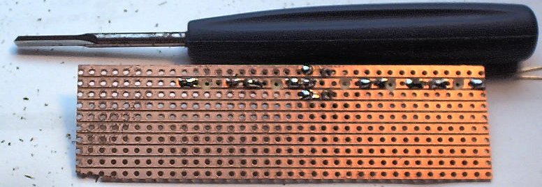
I like to use "experimenting PCBs" with pre-drilled holes and complete connection lines as I think they can save you a lot of soldering.
That's why my designs often fits those PCBs.
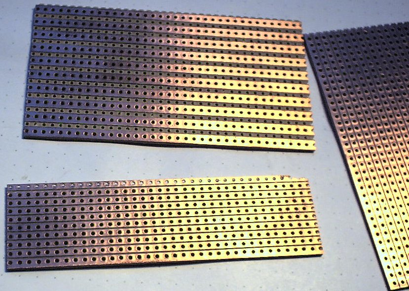
For adapting one axis you need three "stripes" (right next to each other, a board with an "empty" stripe - like top-left -
won't do), so for a normal joystick you should calculate 6 to 7 stripes. You may also want to
put the buttons on the board as well, so add one or two additional stripes. Still that won't use the whole board (the small ones I get from
Electronic Conrad have about 19 to 20 stripes) so you can cut some stripes. I recently found out that you can break the board at the right line
if you're careful, so that could save yourself using a saw.
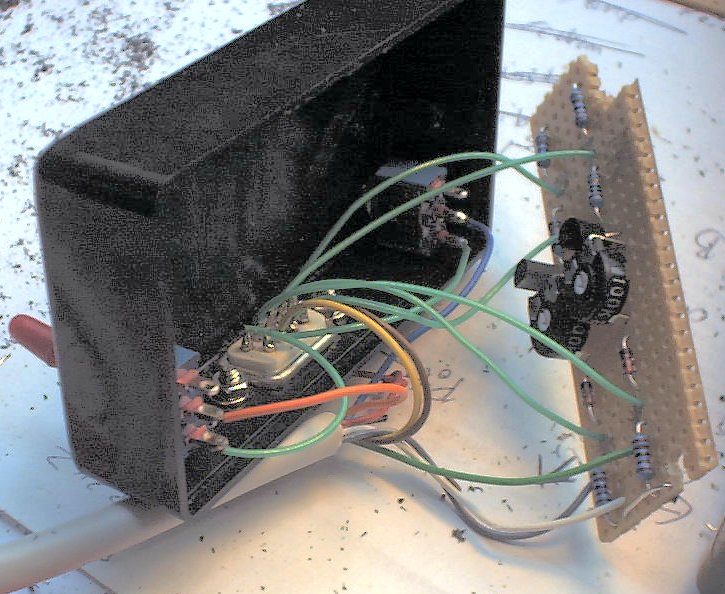
For a really beautiful adapter you should get a small box. I decided to have the 9-pin-connector directly at the box (to plug in the joystick) and have some
inches of cable at the other side with the PC connector at the end. Of course, that's your decision.
I also wanted to be able to connect the extra buttons, but I wanted to be able to disable them (in case the joystick has some other circuits producing problems).
That's why I had to use two switches as well. (and of course drill some holes for them into the box)
Now, that's how you can connect one axis to two buttons (of course you need two of those for a complete joystick)
(the small descriptors are the same as in Tomi Engdahls design)
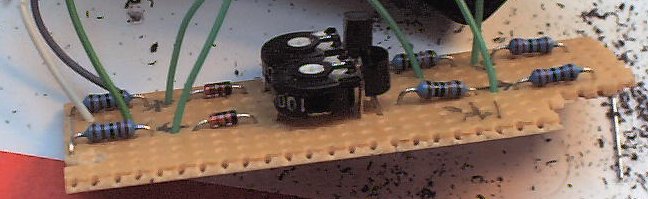
- R1 and R3 are resistors of 2.2 kOhm
- R2 is a resistor of 100 kOhm
- T1 is a transistor BC557 (or equal)
- P1 is a linear potentiometer (variable resistor) with value between 0 and 100 kOhm. It only needs to be centered once
- D1 is a diode (not LED). It is a standard 1N4148
Note that all of the P5V lines have to be connected (I use wires for this). Even though there is no GND in this scheme, note that the buttons connect their
contacts to GND when pressed.
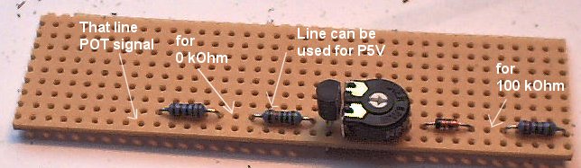
The left contact is for the button that shall produce a 0 Ohm resistor value. This will be UP or LEFT.
The right contact is for the button that shall produce a 100 kOhm resistor value. This will be DOWN or RIGHT.
You might be interested in seeing how the resistor value changes when the buttons are pressed:
- If no button is pressed, the current flows from the right through R3, the diode and part of the potentiometer (should be centered to 50 kOhm).
So you have about 50 kOhm (well, it is a bit more, but still it's about the center), that the computer can regard as center.
- If you press the 100k-Button, the current can't flow from the right (after R3 it flows directly to GND due to the pressed button).
It also can't flow from the left due to the transistor, so the only way is from the top through the complete potentiometer, giving a
resistor value of 100 kOhm. The computer regards this as DOWN or RIGHT.
- If you press the 0k-Button, the current flows from the top through T1 (emitter to base) and R2 to GND (again the button connects to GND).
That moment current flows from E to B of the transistor, the transister starts conducting, so the the current can also flow from the top through the transistor
(resistor value almost zero). The computer regards this as UP or LEFT.
- When both buttons are pressed, TODO!
When soldered to the PCB, the construction looks like that:
If you are using that PCB-line-boards, be sure to break some connections. I use a special tool for this, although
a simple cutter or knife can do.
Of course you have to do that twice (for both axis), connect all P5V to each other, then connect the 9-pin-Connector plus add the wires from the 15-pin-connector.
9-pin-connector
| pin | function | connect to |
|---|
| 1 | UP | solder to PCB at 0k-button for y-axis |
| 2 | DOWN | solder to PCB as 100k-button for y-axis |
| 3 | LEFT | solder to PCB as 0k-button for x-axis |
| 4 | RIGHT | solder to PCB as 100k-button for y-axis |
| 5 | extra button | directly to DSub15.7 or switchable |
| 6 | Button | directly to DSub15.2 |
| 7 | P5V | solder to PCB at one P5V connection point (you can also directly solder to DSub15.1) |
| 8 | GND | directly to DSub15.4 |
| 9 | extra button | directly do DSub15.10 or switchable |
15-pin-connector
| pin | function | connect to |
|---|
| 1 (+9) | P5V | solder to PCB at one P5V connection point |
| 2 | Button 1 | directly to DSub9.6 |
| 3 | Axis 1 (X1) | solder to PCB at output for x-axis |
| 4 (+5) | GND | directly to DSub9.8 |
| 5 (+4) | GND | bridge to DSub15.4 |
| 6 | Axis 2 (Y1) | solder to PCB at output for y-axis |
| 7 | Button 2 | directly to DSub9.5 or switchable |
| 8 | (P5V) | Do not connect |
| 9 (+1) | P5V | bridge do DSub15.1 |
| 10 | Button 3 | directly to DSub9.9 or switchable |
| 11 | Axis 3 (X2) | Do not connect |
| 12 | (GND) | Do not connect |
| 13 | AXIS 4 (Y2) | Do not connect |
| 14 | Button 4 | Do not connect |
| 15 | (P5V) | Do not connect |
Of course you can connect non-used buttons by adding them to your box. You might also want to build a converter for two joysticks (then you need the whole
converting line four times and cannot use the third extra button). I myself connected Button 4 (pin 14) to the cable but left it unconnected in the box. You never
know when it might come in handy.
I think it is rather normal having cable chaos at that time.
Finishing and afterwords
Before you finish everything, connect the adapter (without C64-stick connected) to the PC, activate it as 4-button-gamepad or so and center
the joystick on the screen by tunig the trimmers. You then should connect a C64-stick and see if it functions.
If you are sure that everything works, disconnect the converter from the PC.
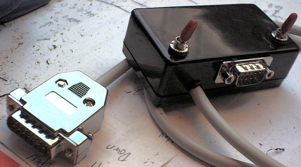
Now tighten all switches and screws, find a way for the DSub-15-cable, close the box and the DSub-15-shell.
The nice things about those boxes is that they hide all the cables so no one can see the chaos inside.
Unfortunately this converter can't really be tested with the Joystick tester described on that homepage. The resistor value always is very high (near 100 kOhm).
It switches to about zero, when the left/up button is pressed, but it only changes very poorly when the right/down button is pressed.
(Still you can see measure the difference). Of course the buttons work just fine.