Back to Technical Index
9-pin-joysticks
Atari, Amiga, C64 and other older computers use the same (or at least similar) joysticks. I will call them C64-Joysticks from now.
The connector on the joystick cable is 9-pin-D-Sub Female, so the connector on the computer is 9-pin-D-Sub male.
It seems that there is a standard for this connector but later on some manufactorers made their own alternatives to this.
| Pin | Function | Alternative |
|---|
| 1 | UP |
| 2 | DOWN |
| 3 | LEFT |
| 4 | RIGHT |
| 5 | POT Y | Extra Button |
| 6 | BUTTON |
| 7 | P5V |
| 8 | GND |
| 9 | POT X | Extra Button |
Digital Buttons
Directions and buttons are used the same way. When a direction (or the button) is pressed, there is a connection between the Pin and GND.
The Directions are digital buttons like the button itself. You could push up+down at the same time but that would be pretty confusing for the C64.
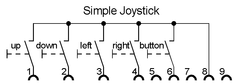
You will notive that it is very easy building your own Joystick (electrically). Still the mechanical plans are more interesting.
Power Supply
For the real basics the power supply isn't really needed. Some Joysticks need it for pretty lights or some Auto-Fire-function. On the C64 a joystick
was only allowed to draw 50mA (100mA due to some other information) from the C64. I believe that this supply might also be needed for the Potis
However some Joysticks have some more sophisticated hardware in them (ICs, transistors) that need power to give out the right button selection.
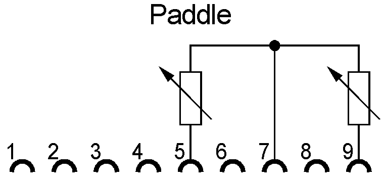
POTs
So what about the POTs? For some games (usually Break-out, Arkanoid and so) you could use the "Paddle". Instead of a joystick
you only had a small knob that you could turn and your paddle on the screen moved like that. With fast turning you could get the paddle from one end of
the screen to another. Normally one player also needed one knob so you could have two players at one control port. As the C64 had two control ports you
were able to use 4 paddles in a game.
Those turning knobs are internally simple potentiometers (variable resistors). I believe they were connected to P5V (due to my old paper guide).
Due to some internet information, the Pots are linear 470kOhm but I can't confirm that information. My C64 paper guide rather reports
a variable resistor from 20 Ohm to 200 KOhm.
When I get my hands on one of those paddles, I will update this information.
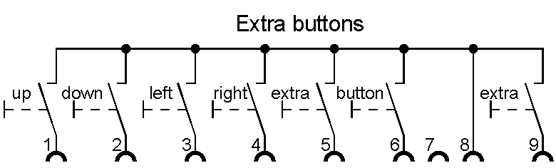
Additional Buttons
Some joystick and hardware simply used the POT wires for additional buttons. That way you could have joysticks with 3 buttons.
Technically it would be possible to have 4 buttons (by using the P5V wire, too) but that would be pretty dangerous. When your computer doesn't know
about your modification, it would send 5V over that wire and when you press Button4 you would connect those to GND. Connecting P5V to GND has very unhappy
consequences from "Heating up" "Sparks" to even "Fire".
Light Pen
It was possible to connect some Light Pen to the C64. You could paint directly on your TV. The C64 found out where you pointed and
reacted by putting a dot there. (Or some other painting methods)I remember trying out one but then giving it back because it worked like crap. Due to my paper guide
pin 6 (the Button pin) was responsible for the pen to work. Apart from that I have no real information about this.