When you read the previous section carefully, you should know that most joysticks are nothing more than 2-4 digital buttons plus 4 variable resistors.
That makes testing them pretty easy. Check if there is a conenction between GND and the pin for the buttons and check the resistor value
between P5V and the pin (unlimited -> no connection, 0->left/up 100-> right/down)
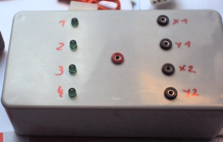
Still you might want to build a real tester. It is much prettier wen there are LEDs showing you the button status.
Also many joysticks don't work without power supply so you will get a wrong value when measuring the resistor.
Such a tester is also interesting if you want to know, how a joystick works "behind the driver". Perhaps you'd like to know how
it maps the additional buttons or so.
It also helps, if your Operating system doesn't recognize the joystick (due to a defect cable or so). I myself had the problem, that wire 6 of a controller
was broken and so the controller just didn't work.
Of course you need a 15-Pin-female connector to plug your joystick into.
As you want to measure the resistor values, you either need four Ohm-Meters or some banana plugs to use an external Multimeter. I recommend the later way.
You need the 4 LEDs for the 4 buttons plus resistors for the LEDs.
Most cheap LEDs want an amperage of 20mA and a voltage depending on their color:
| Color | Voltage | necessary resistor |
|---|---|---|
| red | 2,25 V | 137.5 R |
| green | 2,2 V | 140 R |
| yellow | 2,1 V | 145 R |
Okay, I assume that you know how to solder, have the right holes in your box and only need the electrical information:
Of course you need to connect P5V from your power source to Pin 1 of the connector. Perhaps you should connect to some other P5V-pins, too.
Until now Pin1 sufficed for me.
You also need to connect GND from your power source to pin 4 of the connector. Same as above, you can connect to more, but this one seems to be enough.
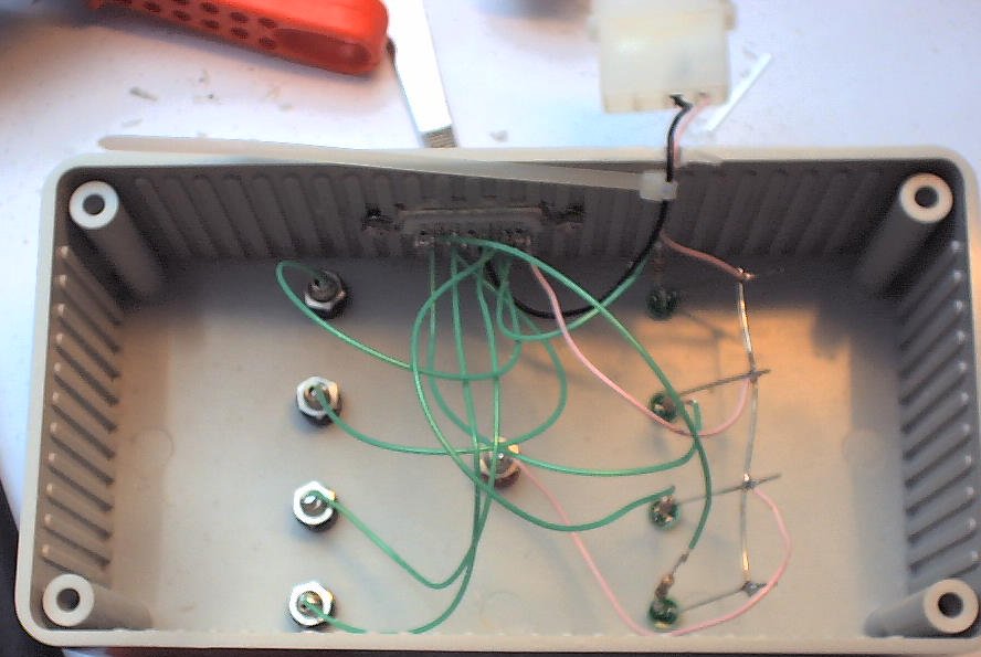
You should solder the resistors directly to the LEDs. Just remember where kathode and anode is. I use to solder the resistor to the kathode and then shorting
the wires so that kathode is still the shorter end.
Connect the anodes of all LEDs together and add a connection to P5V. Also add a connection from P5V to a banana plug (I like to use a red one for this)
Connect the kathode of each LED to the Button Pin of the connector. (e.g. LED for Button1 must go to Pin 2)
Connect each Axis pins to one of the other banana plugs (e.g. X1 to Pin 3). I like to use black banana plugs for this.