Small note: the SNES is also known as Super Famicon
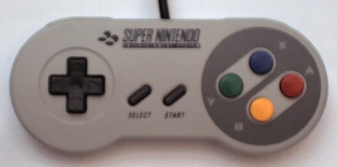
The SNES controller is a beautiful Gamepad:
Look at it! Isn't it a real beauty?
Still that Pad has an enormous disadvantage: It is for SNES only. The average PC is definitely missing a connector
for those wonderful pads.
Still you might want to connect those beauties to your PC. Like you may have guessed, there is a way.
(Else there wouldn't be much sense in writing this guide)
It isn't only possible to connect them to your PC, there is also some software that supports it.
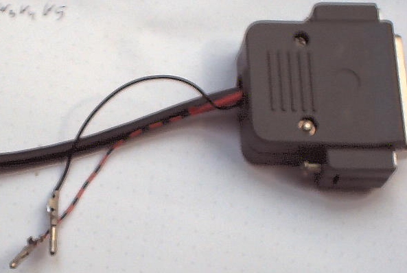
In order to connect your gamepad to the PC you need to build a small adapter. You need to plug it into the parallel port
of your computer. So if a printer or some other hardware is blocking that port you need to unplug it, use a data switch or
install another parallel port. Unfortunately some very new PCs don't have that port any more.
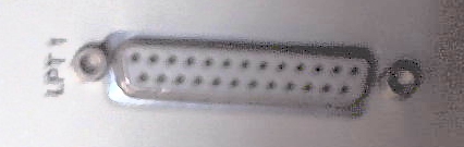
In case you don't know what that port looks like: It's a D'Sub25-pin-female port.
(Don't expect many more of that kind of simple help from me.
If presume you know some technical basics and have soldered once or twice before)
So of course you need a D'Sub25-pin-male plug on the other side. If you are rather new to this, you should try to find one
that you can easily solder with. It's also a big help if it has the pin numbers printed on it. You can get them easily at electronic stores
like "Reichelt" (mail order from germany), "Electronic Conrad" (tends to be a bit expensive, but it has a store in larger cities in germany),
or "Radio Shack" (I've heard that this is the place to choose in US). In case you're not playing with electronics first time, you should
already know your favourite near by.
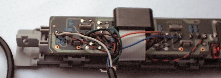
Although it might be possible to build that adapter in a single box, I recommend using some cable. It doesn't need to be very long
(as stated before, the controller cables are rather long themselves), but should suffice to keep some room behind your PC.
More important is the number of wires you need.
Generally you need 4 wires plus one wire for each controller you want to attach. You can save one wire if you want to connect
a power souce directly and not to use the LPT-Port for power.
You can connect up to five Pads to the PC with the right adapter.
I decided to connect two controller. The original SNES has two connectors and it's what the DOS-version of ZSNES supports.
Also I only had two connectors. That makes a total of six wires for my adapter.
Many guides on the net recommend buying an extension cable and cutting it. Some people cut their controller cable and
attach a more common connector (like D'Sub 9) and then build another small adapter for connecting that pad to SNES again.
I wanted to have a "native" connector, so I decided to open a real SNES and use the controller from there.
On EBay you can sometimes find a defect SNES. Let me tell you that most defect SNES at least still have a working connector for
the controller pads. We don't even need any electrical function, we just need the mechanical connectors.
It seems the first thing going down the drain is the antenna connector - at least thats the most common mistake I found.
So when the TV set can't find the channel with the SNES signal any more, many people consider their SNES as garbage.
If only the antenna plug is defect, you can have your SNES up in hardly any time at all:
On the back side of the hardware, there is another connecor called "multi-out". Sometimes it is hidden behind some plastic cover
that you can easily remove.
Now you just need an adapter cable (this connector is the same on N64 so you can use the cables from there). Very common is the
Adapter to three cinch connectors (1 composite video plus 2 audio channels). Then connecting those cables to your TV-card input
or your TV-set using a Cinch-to-Scart-adapter is rather easy.

I've also seen an adapter to S-VHS. So the quality of the RF-connection really wasn't the best you can get.
Well, I kind of got away from the topic. Let's just assume that we have a SNES that really is garbage except for the connector.
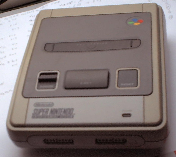
You could use a saw to get out the connectors with brute force. I rather prefer using screwdrivers. So turn the SNES over
and unscrew the six screws.
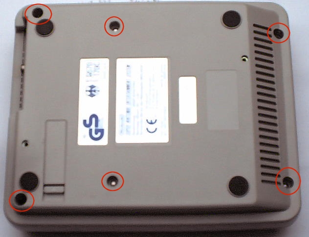
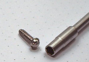
Okay, This will get a bit difficult: Nintendo uses some very interesting screws in their hardware. They are a bit uncommon so you
won't find them in your average screwdriver set. At the SNES you will find outer-hexagon screws. If you don't care about the SNES you
can try to drill those screws down. You can also search for a special screwdriver at "Conrad", "Reichelt" or "Radio Shack". Although
I have read, that the exact SW-value is 4.2, I found it much easier aquiring a 4.0. It's not hard turning the screws with this one.
(The Conrad order number for my one is 824283).

Put the screws where you won't lose them and open the console. Beware! You are about to see the inner side of a
Super Nintendo Entertainment System.
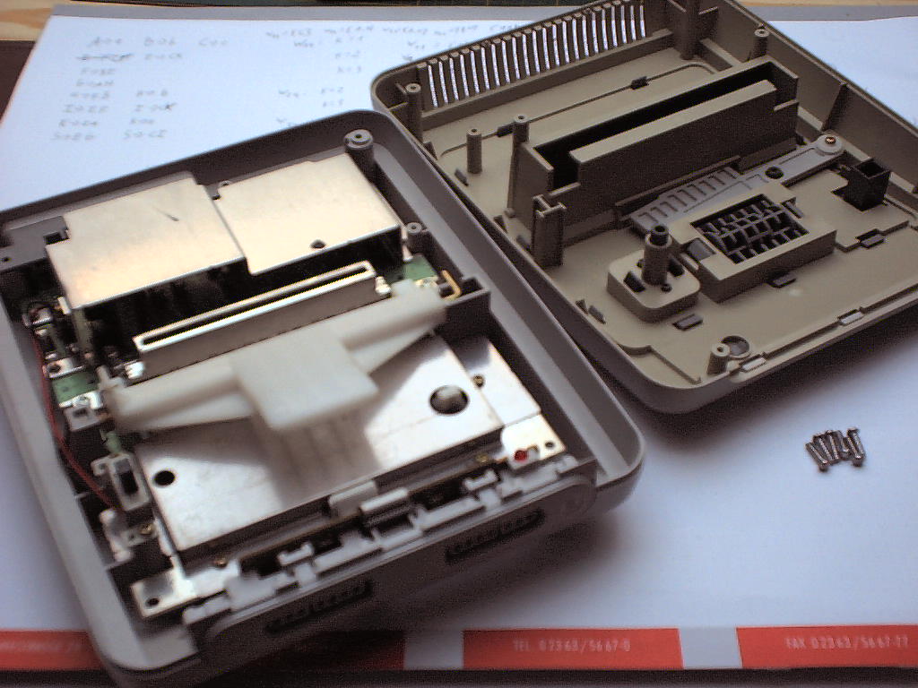
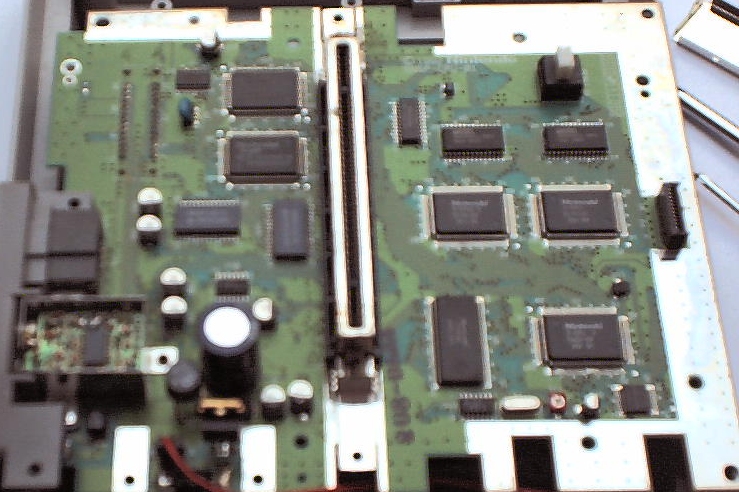
Well. Nothing much to see. Lot's of things are covered with metal sheets. Still you might find the reset button, the power switch
and the sophisticated (grinning) Eject-button.
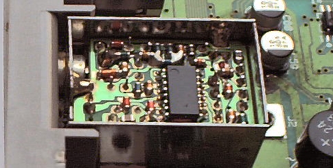
In case you wonder: Even without the metal sheets you won't find wonders there. Just a lot of black ICs
some labeled CPU, some DSP etc. You can also peek inside the antenna converter box. Still it's rather boring,
but I never promised you roses.
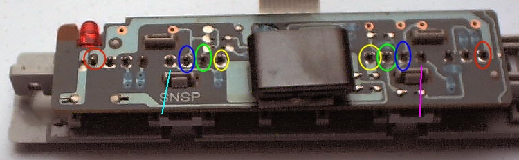
Let's turn to the joystick connector again.

You can easily lift the board with the connector. Then pull the flat cable out of the connector (shouldn't be hard) and
you have your precious board disconneted from the rest of the console. You can now put away the rest of the console.
Perhaps you want to use the power supply or build your own backup device or something. All of this is beyond this guide.
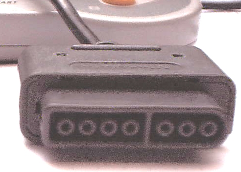
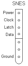
Now it's time to learn a bit about connectors: The SNES-connector has 7 pins, of which only 5 are used:
In case you open the cable, you might find that table helpful. I cannot guarantee that all SNES controllers in the world
have that same colouring, but i found it on some american homepages, on some european homepages and in my own controllers so
I think it's not uncommon.
| Pin | Color |
|---|---|
| Power | white |
| Clock | yellow |
| Latch | orange |
| Data | red |
| Ground | brown |
Now let's learn some things about the PC parallel port:
| Parallel Port Pin | SNES board | insert your color here |
|---|---|---|
| 18-25 | GND | |
| 3 | Latch | |
| 2 | Clock | |
| (5,6,7,8,9 diodes - if used for power) | Power | |
| 10 | Data for Pad 1 | |
| 12 | Data for Pad 2 | |
| 13 | Data for Pad 3 | |
| 15 | Data for Pad 4 | |
| 11 | Data for Pad 5 |
Well, that should be it. Try connecting it with your PC and find out if DirectPadPro recognizes the controller. There may be some problems
with too new Operating Systems preventing hardware access (NT systems or XP, 2000 or so) better try it with Win98 or so.
In case you use an external power supply, turn it on before you plug in the LPT-Plug. I've heard that such constructions
can drain power from and damage the LPT-port if they don't get the power they want. It never happened here, I just wanted to warn.
People get the strangest ideas, so note that you can't simply put a multitap on your PC adapter and connect more joypads.